
Pump matching
The inverter is matched from the pump nameplate and from the duty of the site, not from a power figure alone.
Installer Support
For solar installers, pump installers, irrigation installers and solar pump system integrators: the workflow that takes an existing AC pump from its nameplate to a commissioned installation, and the support that runs with it.
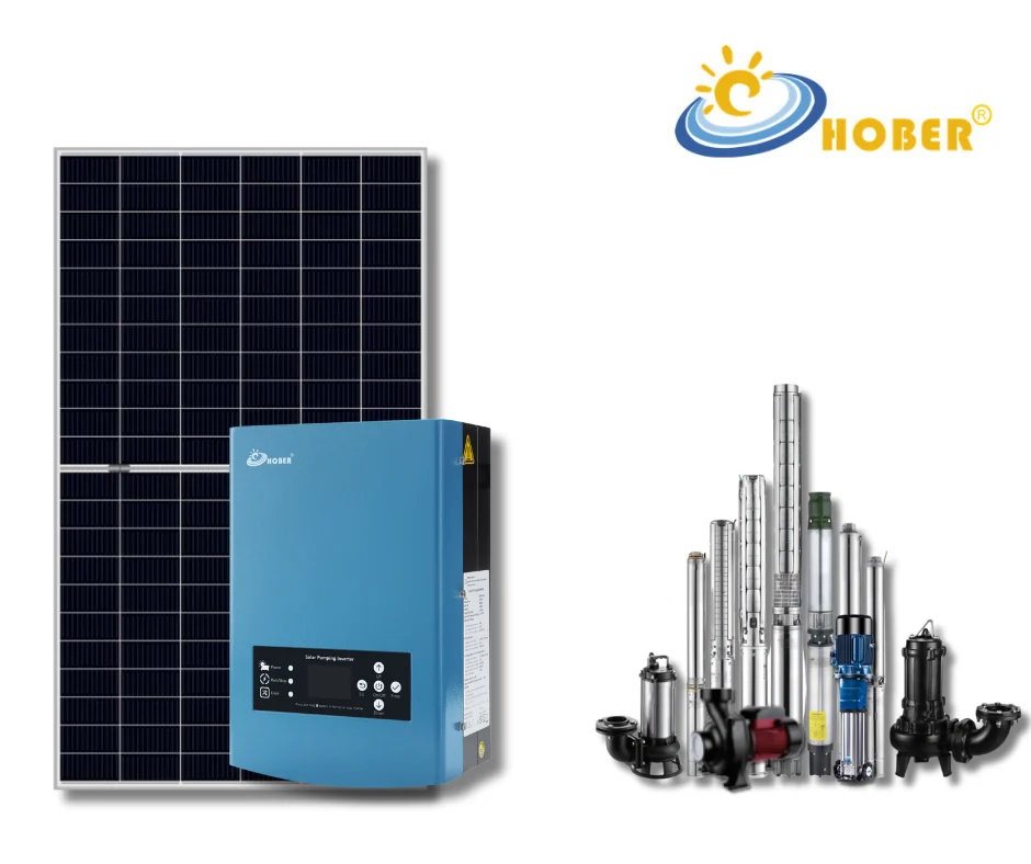
The inverter that drives the existing pump
01 / The workflow
Nine stages, in the order they are worked through. Each one settles a question that would otherwise come back on site.
“How do I convert this AC pump to solar correctly?”The answer is a sequence rather than a product, and every stage depends on the one before it.
The order is the point. A stage that is skipped usually comes back as a fault after commissioning, which is why the workflow is worked through rather than picked from.
02 / What we need from the pump
A compatibility check starts from what the pump is and what it has to do. Send what you have and the check works from that.
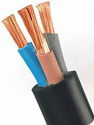
The cable run is part of the check
03 / What the support covers
Six areas an installer can bring to us, from the pump that is already on site to the fault that shows up a season later.
The inverter is matched from the pump nameplate and from the duty of the site, not from a power figure alone.
The array, the module data, the string design and the combiner box are worked out for the site and for the pump that was selected.
The run from the array to the inverter and from the inverter to the pump, the cable, the output filter or reactor, grounding, and lightning protection where the site calls for it.
The settings an installation needs, including water level control, dry-run protection and hybrid solar with grid or generator operation where the selected model and the site allow it. Each one is configured for the installation, never assumed for every model.
Optional flow metering and 4G or WiFi remote monitoring where the installation includes them, with the running data and the fault information they report.
Support through the first run and, afterwards, fault analysis from the readings the installation reports, so an installer does not have to drive back to site to answer a question.
Water level control, dry-run protection, hybrid grid or generator input, flow metering and remote monitoring are options rather than standard functions: each one is confirmed against the selected model and the installation.
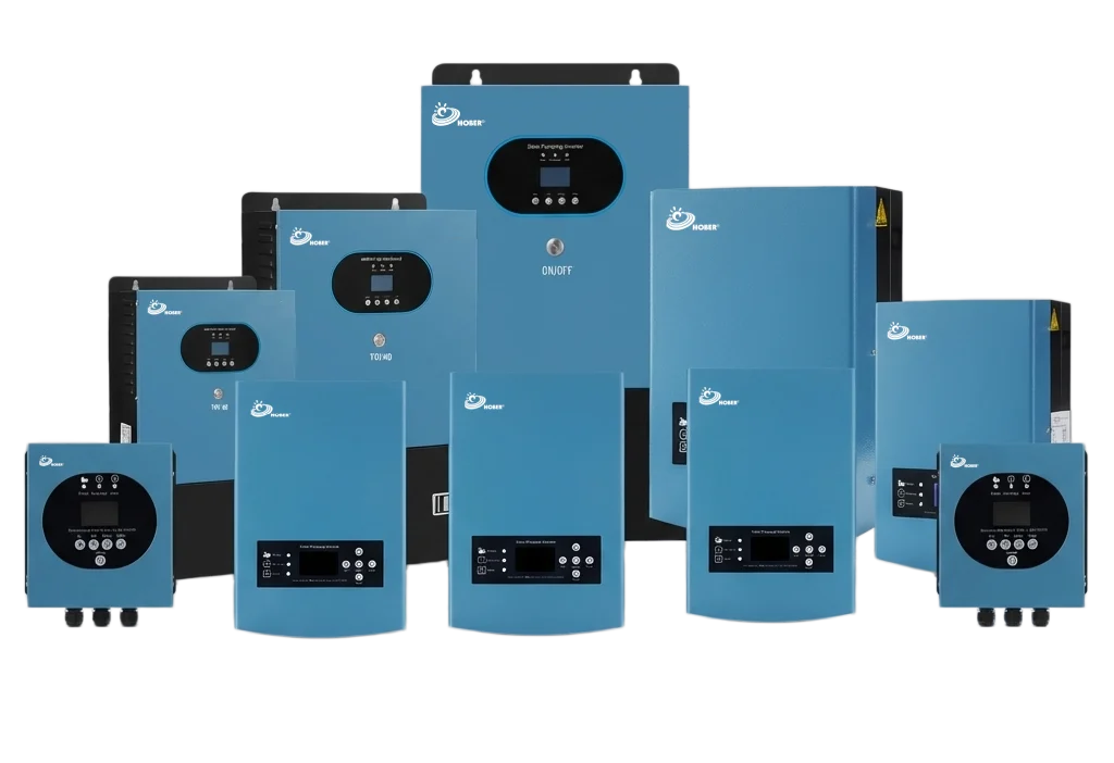
The parameter list and the readings come from here
04 / After the installation
Questions that arrive after commissioning are answered from what the system is doing now, so the first reply can be the useful one.
Those four usually settle the question without a site visit, which is the point: a visit is kept for what a reading cannot show.
05 / Questions
No. The motor has to be one a solar pump inverter can drive, and the pump has to suit the duty the site needs. Those two things are what the nameplate check and the compatibility check settle, and where the answer is no we say so before anything is proposed.
The power, voltage, phase and rated current on the motor plate, the pump model, and how the installation is powered today. A clear photograph of the plate is enough to start the check.
Where a hybrid model is selected and the site is wired for it, the installation can run from the grid or a generator when solar is not enough. It is confirmed per installation rather than assumed, so tell us what the site has.
Send the same details. The check works from the pump and the site rather than from the order, and we say what can be supported. Where the pump is not suitable for a conversion, we say that too.
Read the motor nameplate and its own wiring diagram first, then confirm that the model you are fitting supports that motor’s phase arrangement: a setting in the menu does not make an incompatible motor and drive combination suitable. Before anything is run, check the approved lead connections, the motor voltage, the rated current and the frequency against that model’s manual, save the settings and read them back.
Set it from what the pump and the motor are allowed to do, never from the lowest value the drive can be programmed to. At that speed the pump still has to hold the system head and deliver the flow its duty needs, and the motor has to keep the cooling it depends on — the pump curve, the motor instructions and the water level decide the figure, not the drive. The low-power stop, the restart delay and the hysteresis are set from those same data to the model’s own manual, and the flow actually delivered is confirmed at commissioning.
A controlled ramp-down is possible while the drive still has energy and authority over the motor, but it cannot be promised when the array output collapses suddenly: a commanded soft stop and a protective shutdown on low voltage are different events, and the second one follows the protection rather than a ramp. Ask for the behaviour and the permitted deceleration range of the model you are fitting, and treat the pump, the check valves and the pipework as part of the question where an abrupt stop causes surge. Protection is never slowed or disabled to make a stop look smoother.
Only the level inputs, the common terminal and the contact logic that model’s manual states for them, and only with the kind of device that input is made for: a volt-free switch, a powered transmitter and an electrode arrangement are not interchangeable. The normally-open or normally-closed behaviour, the input configuration and any restart delay are matched to that wiring diagram, and the response to a disconnected sensor is tested deliberately rather than discovered in service. No external voltage goes onto an input the manual does not describe, and no terminal number is taken from another model — send the model and the sensor you plan to fit, and the pair is confirmed for you.
Next step
Share the motor nameplate, the duty the site needs and how the installation is powered today. Our sales team reviews the conversion and answers with the equipment that fits the pump and the site.