
Motor compatibility review
Nameplate, terminal and starter analysis before quotation.
FACTORY-DIRECT SOLAR PUMP INVERTER
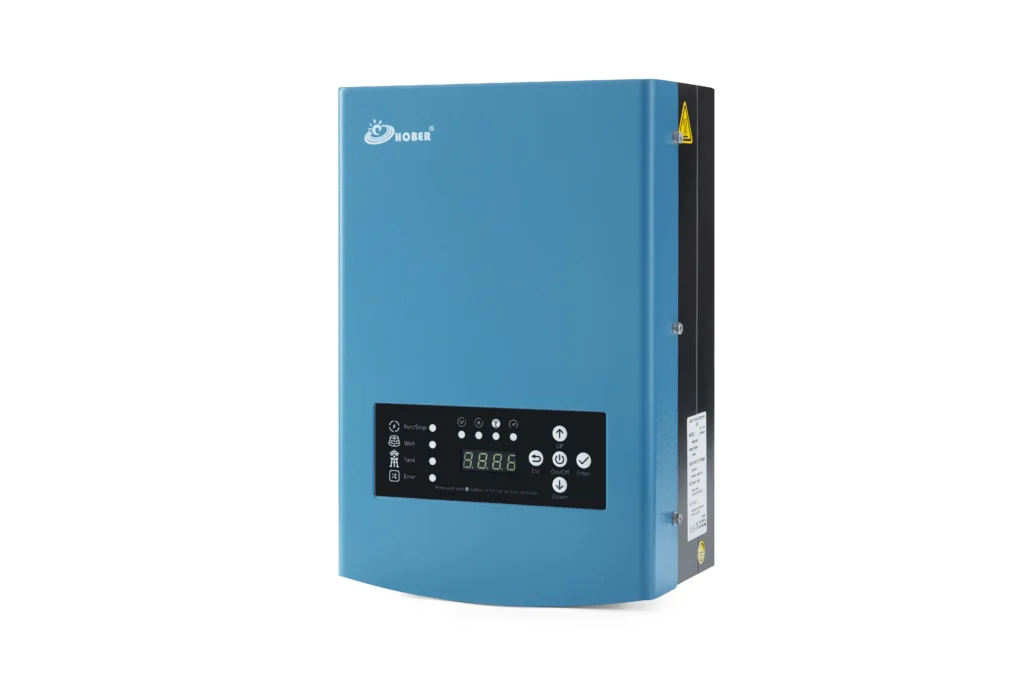
Keep a compatible AC pump. Add solar panels and a HOBER solar pump inverter. Our team helps you verify motor wiring, match the inverter and size the PV array before installation.
Compatibility depends on winding access, starting components, motor data and the exact model.
02 / HOW IT WORKS
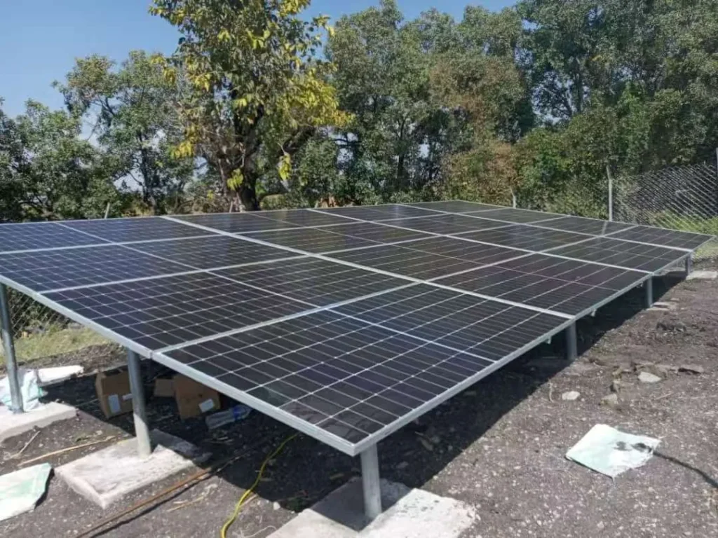
PV panels feed DC power to a compatible solar pump inverter, which drives the motor through its supported single-phase pump output. The motor's winding terminals are connected by the approved wiring procedure for the exact model.
03 / MOTOR COMPATIBILITY
| Verify before selection | What to provide |
|---|---|
| Supply and motor type | Nameplate: 220–230 V, single phase, rated Hz |
| Rated load | Motor kW/HP and full-load current (A) |
| Motor connections | Photo of the motor terminal box and its connection diagram |
| Starting components | Capacitor type(s), internal start switch or relay, starter box |
| Access to windings | Common (C), Start (S) and Run (R) identified and connected as approved |
| Hydraulic application | Pump type, total head, target flow, daily water need |
| PV system | Panel wattage, Voc/Vmp, strings, site temperature, grid backup |
A single-phase nameplate alone does not establish compatibility: some two-wire sealed pumps and internally switched or electronically controlled motors need separate engineering review and may be unsupported.
04 / WIRING GUIDE
The three-winding-lead method of HOBER's Single Phase Pump Connection Guide V3.0, for motors and HOBER models approved for it. A qualified electrician does the work with the power isolated.
Remove the capacitor for this approved three-lead connection method. Do not apply the procedure to every single-phase motor. Never wire by colour alone.
Step 1
Disconnect the PV and AC supplies and lock out the equipment. Confirm zero voltage with a suitable meter and discharge the capacitors as the manufacturer instructs. Check the pump nameplate and terminal diagram against the exact model manual.
| Leads tested | Resistance |
|---|---|
| Blue ↔ Black | 39.3 Ω |
| Black ↔ Brown | 24.8 Ω |
| Blue ↔ Brown | 14.6 Ω |
The largest reading, Blue–Black, is the S–R pair, so Brown is C. From Brown, the smaller reading is to Blue and the larger to Black, so Blue is R and Black is S. For this motor: Brown = C, Black = S, Blue = R.
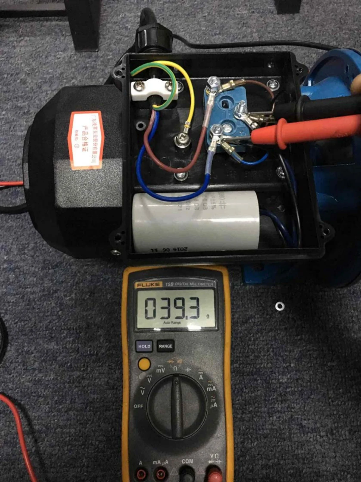
The numbers and the wire colours are one documented motor, not a specification for another: readings vary with winding design, temperature and meter accuracy, so check the manufacturer documentation.
Step 2
With the circuit isolated, measure resistance across each pair of the three winding leads. The largest pair is usually S–R, the remaining lead is C, and C–R usually reads lower than C–S. This is a diagnostic aid only, not a replacement for the manufacturer's diagram, and wire colours prove nothing.
Step 3
Remove the capacitor before making the approved connection. Never leave a run or start capacitor across the inverter output leads. If the motor has an internal relay, switch or unreachable capacitor, stop and contact HOBER.
Step 4
Connect C, S and R to the outputs named in the exact HOBER model manual. The historical PDF's red → C, blue → S and yellow → R is one example and must be verified. Connect PE / earth separately, as that manual requires.
Step 5
Check motor mode, power, rated current, nominal voltage / frequency, protection settings and the model's PV voltage window. Inspect the terminals, cable routing, earthing and any exposed conductor.
Step 6
Run the initial tests the inverter and pump manuals give. Record the motor current, direction or flow, temperature and any fault codes. If current rises, flow is abnormal or the motor overheats, stop and recheck the wiring.
05 / SAFETY & COMMISSIONING
Nothing is energised until the capacitor is removed from the circuit and C / S / R are confirmed by measurement.
When to stop
06 / MODELS
Start with the motor's rated current and winding arrangement, then confirm the exact inverter model and DC input range.
| Model | Listed rated inverter power | Listed solar DC input | Listed output |
|---|---|---|---|
| HSPH750LB | 0.75 kW | 80–450 V DC | 220 V, single phase |
| HSPH1500LB | 1.5 kW | 120–450 V DC | 220 V, single phase |
| HSPH1500L | 1.5 kW | 200–450 V DC | 220 V, single phase |
| HSPH2200L | 2.2 kW | 200–450 V DC | 220 V, single phase |
| HSPH3700L | 3.7 kW | 200–450 V DC | 220 V, single phase |
| HSPH5500L | 5.5 kW | 200–500 V DC | 220 V, single phase |
| HSPH7500L | 7.5 kW | 200–500 V DC | 220 V, single phase |
The DC input column is the listed operating window, not a safe PV open-circuit design limit. The verified MPPT range, minimum start voltage, absolute maximum PV Voc and grid/AC backup support are confirmed for your exact model.
| Model | Listed rated inverter power | Listed solar DC input | Listed output |
|---|---|---|---|
| HSPH11KL | 11 kW | 200–650 V DC | 220 V, three phase |
| HSPH15KL | 15 kW | 200–650 V DC | 220 V, three phase |
These models drive three-phase motors and are not the single-phase output models above.
07 / SUPPORT
Nameplate, terminal and starter analysis before quotation.
Vmp/Voc, string configuration and connection drawings for the approved model.
Installation guidance, parameters and fault diagnosis.
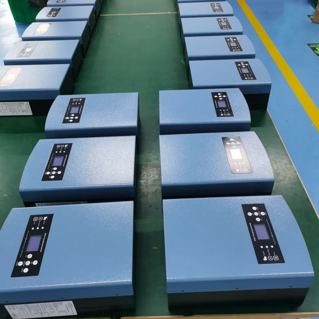
Factory supply for pump distributors, solar installers and project buyers. OEM/volume enquiries welcome; availability and MOQ confirmed by sales.
08 / FAQ
Capacitor: HOBER's three-lead method removes the motor capacitor from the circuit, and applies to an approved motor — not to every single-phase motor.
Often possible for compatible motor designs. HOBER first needs the nameplate, current and connection details to confirm the inverter and wiring method.
For the specific three-lead single-phase motor wiring method documented in HOBER’s guide, yes. The capacitor must not remain connected in the approved inverter-driven circuit. This does not mean every single-phase motor can be modified in this way.
Do not assume this is acceptable. The documented approach requires access to and correct identification of motor C/S/R winding points. Send the motor’s connection diagram for review.
Use the motor wiring diagram and qualified electrical testing. In the guide’s specific example, three pairwise resistance readings help identify the terminals; wire colours alone are not reliable.
Not automatically. Internal starting hardware and winding access must be assessed. HOBER must approve a suitable connection method or advise that the motor is unsupported.
This depends on motor current/power, expected pumping duty, panel Vmp/Voc, temperature and the chosen inverter’s verified input limits. Request model-specific PV sizing rather than relying on a fixed panel count.
HOBER lists certain 220V three-phase output models separately. They must not be confused with the single-phase output models on this page.
Yes. Share the main pump models in your market and expected volume to discuss approved motor matching, technical documentation, samples and wholesale terms.
There is no one margin that suits every single-phase pump. The selected model has to be approved for that motor, and its usable continuous output current — after any derating the installation needs — has to cover the motor. Winding design, the starting circuit, the capacitor arrangement, the load and the site’s ambient temperature all change the answer, so a larger kW label on its own does not establish compatibility. Send the motor nameplate with its wiring details and the margin is checked against the exact model.
09 / REQUEST A MATCH
Every figure may be left open — the nameplate photograph is the surest way to be exact, and what is missing we confirm with you before a drive or a range is proposed.