
Solar Pump Sizing: Check Pipe Losses Before Adding PV Panels
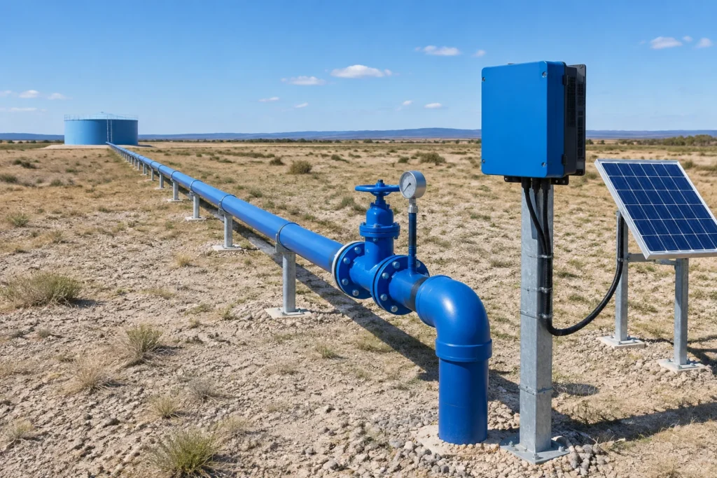
Quick answer
Before increasing the PV array, check whether the pipeline is making the pump work harder than necessary.
When an existing AC pump delivers too little water after conversion to solar, adding panels may look like the obvious solution. Before changing the array, establish whether the constraint is available electrical power, the pump’s operating range or the hydraulic system.
For distributors and installers, this distinction affects both the quotation and the service call. More PV capacity cannot be assumed to correct a restricted pipeline or an incorrectly assessed duty point.
What a recent irrigation study found
A September 2026 paper in Renewable Energies modelled Palestinian deep-well irrigation with a 130 m static head, 10 m drawdown allowance and water storage.
Its comparison produced the following results:
| Model result | 4-inch delivery pipe | 6-inch delivery pipe |
|---|---|---|
| Peak total dynamic head | 159.2 m | 142.8 m |
| Peak drive-input power requirement | 99.6 kW | 89.4 kW |
| Minimum PV capacity meeting the study’s water-deficit criterion | 170 kWp | 165 kWp |
These are simulation results, not measurements from a HOBER installation. The weather sequence was representative rather than measured, and pump performance used aggregate efficiency assumptions instead of complete manufacturer variable-speed curves. The values support preliminary comparison, not a transferable equipment specification.
Source: Abu Latifeh and Khatib, published September 15, 2026.
Why the pipeline belongs in the sizing calculation
Total dynamic head describes the head the pump must overcome at the required flow. For a typical borehole-to-tank or irrigation system, the assessment includes:
- Elevation difference from the pumping water level to the delivery point.
- Required pressure at the delivery point.
- Friction and local losses through pipes, fittings, filters and valves.
If lift is measured from the actual pumping water level, drawdown is already included. Adding drawdown again would overstate the requirement.
Borehole depth alone is insufficient: pump installation depth and pumping water level are different measurements.
PVsyst’s pump model documentation treats flow, head and electrical input as linked operating variables. It also identifies a head-dependent threshold below which useful flow stops. A motor turning at low speed therefore does not, by itself, prove that water is reaching the tank.
A practical review before increasing PV capacity
The following is HOBER’s recommended review sequence for a distributor or installer preparing a retrofit proposal.
1. Define the water requirement
Record both the required flow in m³/h and the daily volume in m³/day. Include operating season, delivery pressure and any storage available.
A peak flow requirement and a daily water target answer different questions. Both belong in the project brief.
2. Check the actual pipe dimensions
Use internal diameter, material, length and fittings. Nominal pipe size alone may not identify the bore available to the water.
Compare alternatives at the same required flow. Include installation cost, pressure rating and the pump’s resulting operating point before recommending a larger pipe.
3. Confirm the pump duty point
Obtain the exact pump model and its manufacturer Q-H curve. Check absorbed power and the permitted operating range as well as flow and head.
For solar operation, assess the relevant speed range. Where supporting curves are unavailable, treat the result as preliminary and request engineering confirmation.
4. Match the inverter separately
Collect motor voltage, phase, frequency, rated current and rated output power. Confirm motor compatibility and use the selected inverter’s documented ratings and installation limits.
The drive-input power figures in the research table are electrical input requirements for that model. They are not motor nameplate output ratings and should not be copied directly into an inverter selection table.
5. Evaluate water delivery over time
Compare candidate arrays against the water requirement and storage behaviour. A proposal should identify when shortages may occur, rather than reporting annual production alone.
What to record during a low-flow service visit
Capture readings during the same stable operating period:
| Measurement | Purpose |
|---|---|
| PV input voltage and current | Establish the electrical conditions reaching the inverter |
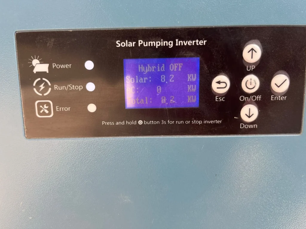
| Output frequency, motor current and alarms | Record the drive’s operating state |
| Flow and delivery pressure | Compare actual hydraulic performance with the required duty |
| Pumping water level | Update the lift under operating conditions |
| Filter and valve condition | Identify restrictions requiring inspection |
Use qualified personnel and the equipment’s measurement procedures. Compare the record with the approved design before changing settings or components.
Start with the site data
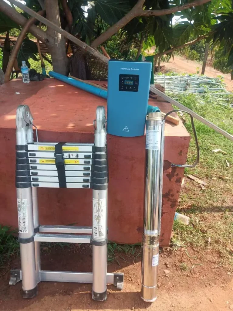
For an existing pump, use HOBER Solar Pump Inverter Selection. For a new pump set, use New Solar Pump Selection.
Include the pump nameplate, Q-H curve and pipeline details with your inquiry. The pipe friction loss calculator can support the hydraulic assessment; final pump, inverter and PV matching still requires the project data.
Project step
Need flow data, constant pressure or remote monitoring on a pumping project?
Send the water source, the required flow, the total head and the pump voltage — HOBER answers with a matched configuration.
References
- Abu Latifeh, S. Y., and Khatib, T. Stakeholder-informed techno-economic design of a standalone photovoltaic water pumping system for irrigation in Palestine. Renewable Energies, September 15, 2026. Original paper.
- PVsyst. Pump — Model description. Official documentation. Accessed October 26, 2026.